


Power Integrity Measurement Tips with the MXO5 and S10 - Capturing Large Signal Phenomena with a TPSM828303A PDN
- Tyler Huddleston

- 2 days ago
- 6 min read
Large signal measurements are essential to Power Distribution Network (PDN) validation. By stressing the PDN, they reveal transient phenomena that are otherwise difficult to surface. This article discusses capturing large signal phenomena with the Picotest P2105A (S10) Transient Load Stepper browser probe. We recently explored Large Signal Phenomena using the MXO5 - Sequential Trigger Measurement Setup.
PDN large signal analysis
PDN large signal analysis evaluates the effect of abrupt current changes. These are typically significant, nonlinear steps that emulate sudden load changes, such as a processor or logic function turning on or off. Unlike small signal analysis, which operates in the frequency domain and focuses on small, linear variations around a bias point, large signal analysis captures nonlinear and transient behaviors. Both types of analysis are essential for comprehensive PDN validation.
Large signal analysis focuses on phenomena such as transient behavior and step responses. It is especially useful for characterizing and revealing:
The mitigation of parasitic inductances by the VRM and decoupling capacitors
Positive and negative voltage overshoot
Ringing and stability concerns
Voltage droop
Engineers typically assess pass/fail criteria by checking whether the voltage deviations stay within the load’s acceptable tolerance range.
One key source of large signal effects is the energy stored in the output inductor of a switching regulator. This stored energy drives the large signal response according to the following relationship:

When the VRM momentarily switches off during a load dump, it releases this energy onto the PDN. By manipulating the phase between the VRM’s switching frequency and the load’s frequency, we can intentionally create and evaluate large signal effects.
How to make a large signal measurement
A PDN can be excited by a current step with standard benchtop equipment and a transient stepper. A signal generator typically controls the transient stepper, while an oscilloscope captures the PDN’s response.
Keep in mind that the PDN’s transient response can vary significantly depending on the point in the VRM’s switching cycle where the step occurs. Even with the same load and PDN, the response can vary from cycle to cycle, so a single step is not sufficient. Instead, periodically stepping the load by a square wave and adjusting the signal generator’s output frequency covers more phase differences between the VRM and the signal generator’s switching cycles and thus yields a more complete picture of transient performance.
Placing a voltage-controlled load onto the PDN is straightforward with a transient load stepper probe like the Picotest P2105A S10. Driving it with 5 V applies a selectable resistive load onto the PDN, while 0 V removes it. Simply connect it directly to a signal generator, set the output to a 0-5 V square wave operating anywhere from DC to 50 MHz. Use an oscilloscope to measure the PDN’s voltage response to the load steps.
You can also use the Arbitrary Waveform Generator (AWG) in an oscilloscope like the Rhode & Schwarz MXO58 to drive the S10 stimulus. However, make sure to insert a coaxial isolator – such as the Picotest J2115A – to break the ground loop between the measurement probe and the load stepper probe tied to the same ground plane within the oscilloscope. Otherwise, you will introduce measurement error in the form of ringing, overshoot, and undershoot noise.
The S10 uses GaN FETs to achieve sub-500 ps switching speeds. It's a browser-style tip with a 70-mil pitch that allows direct placement across the PDN, often at a depopulated 0603 footprint. This setup enables localized excitation by placing the step load at various locations on a PDN.
The Picotest P2104A transmission line probe is recommended for accurate signal measurements of the PDN’s large signal response. It is an effective option for measuring single-digit mV with high noise immunity.
To capture the nonlinear voltage responses in detail, synchronize the trigger with the signal generator’s switching output. Before making the connection, though, always check the voltage level from a signal generator’s Sync or Trigger output to ensure it will not exceed the scope’s input limits. Use an inline attenuator if necessary to protect the scope. Most scopes are rated for a 5Vrms max input.
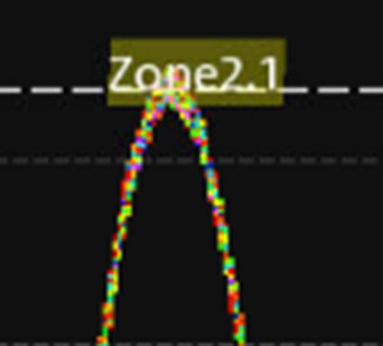
A window or zone trigger can also help isolate clear waveforms and is well worth exploring – especially if you are only familiar with triggering on edges. On the MXO58, you can easily draw a zone to capture the top of the largest peaks to capture the most relevant transient behavior or to capture the worst-case transient response.
Further, the 12-bit resolution, huge amount of memory, and extremely fast acquisition rate available on the MXO58 support these high-accuracy power integrity measurements.
Measurement setup
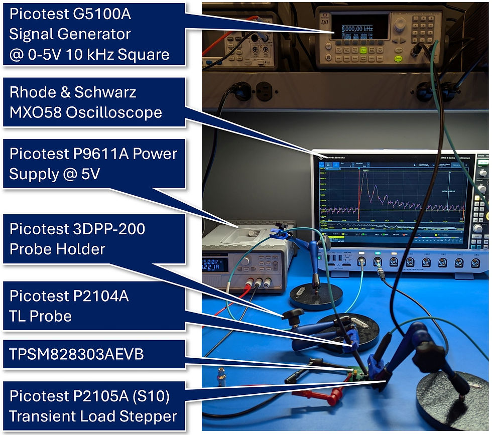
I recently observed large signal phenomena while characterizing the transient response of the TPSM828303AEVM evaluation module using the following equipment:
Transient stepper probe (1.6 Ω resistor head): Picotest P2105A S10
Measurement probe: Picotest P2104A transmission line probe
Oscilloscope: Rhode & Schwarz MXO58
Signal generator (0 to 5 V, 1 kHz to 10 kHz with Sync output): Picotest G5100A
Power supply (5 V): Picotest P9611A
Probe holders: 3DPP-200

The TPSM828303A is a very compact (3 mm x 3 mm) package and efficient voltage regulator module (VRM) from Texas Instruments’ MagPack family. What makes it particularly interesting is its use of integrated magnetics (inductors) on the package. This integration reduces solution size, minimizes parasitic inductance, and simplifies layout—ideal for space-constrained designs like high-density FPGAs, processors, and advanced PDNs. Despite its small footprint, the module offers high efficiency across a wide load range, low output ripple, and fast transient response, making it a strong candidate for modern digital power applications.
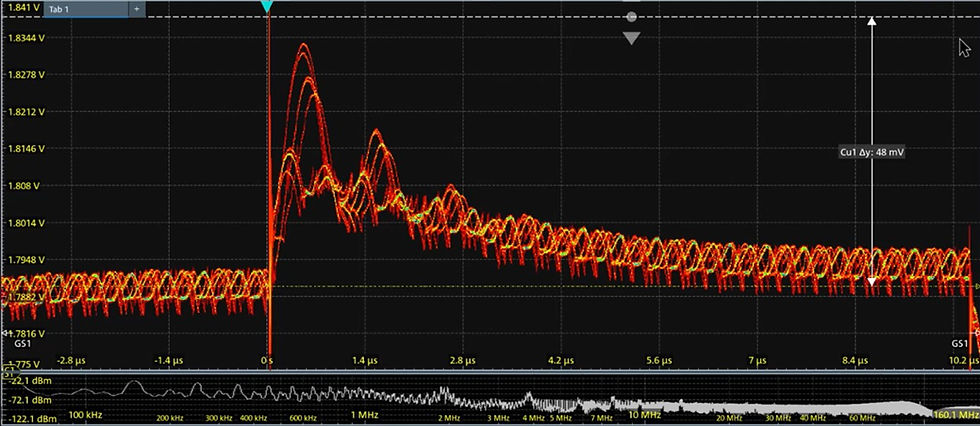
In the measurement setup, the TPSM828303A’s output was configured to 1.8 V. The load current was stepped using the P2105A S10 probe fitted with a 1.6 Ω resistor head, drawing approximately 1.125 A – about one-third of the VRM’s maximum rated output. Channel 2 of the oscilloscope was triggered by the Sync output from the signal generator, with a 3 dB attenuator in line to protect the input. Channel 1 captured the resulting transient response across the PDN.
The scope capture below reveals that the peak transient varies by about 20 mV from cycle to cycle, even though the load switches at a constant rate. Depending on the application, this level of variation could mean the difference between meeting or failing a compliance spec. Testing for such behavior is not straightforward. However, as this setup demonstrates, using the MXO58, the S10 load stepper, and the P2104A probe, we can reliably detect and analyze such large signal effects, providing a practical and effective method for validating PDN designs.
To capture the largest response in detail, I added a zone trigger as shown below.

Conclusion
Power integrity spans the entire path from the voltage regulator to the load, and each application demands tailored PDN design and validation. Large signal analysis plays a critical role in this process, revealing how the PDN responds under real-world, dynamic conditions. Ultimately, it is the voltage deviations – what the load actually sees – that determine system reliability. Validating that these responses stay within spec requires intentionally stressing the PDN to expose potential weaknesses.
While the measurements themselves can be straightforward – often just placing a browser probe and configuring an oscilloscope – the quality of your results depends heavily on the precision and bandwidth of your tools. Investing in high-performance measurement equipment, such as a capable oscilloscope, clean signal generator, and low-intrusion probes, ensures you can capture fast transients accurately and make confident design decisions. As PDNs continue to tighten with lower voltages and higher speeds, this kind of detailed validation becomes not just beneficial – but essential.
References
DesignCon 2024 - Design, Simulation and Validation of a 2000-Amp Core Power Rail by Steve Sandler, Benjamin Dannan, Heidi Barnes, Ben Ezra Idan, and Yu Ni


Comentários